A scene-coupled feedback instrument, introduced from its canonical model, and the Markov-kernel formalism that describes it.
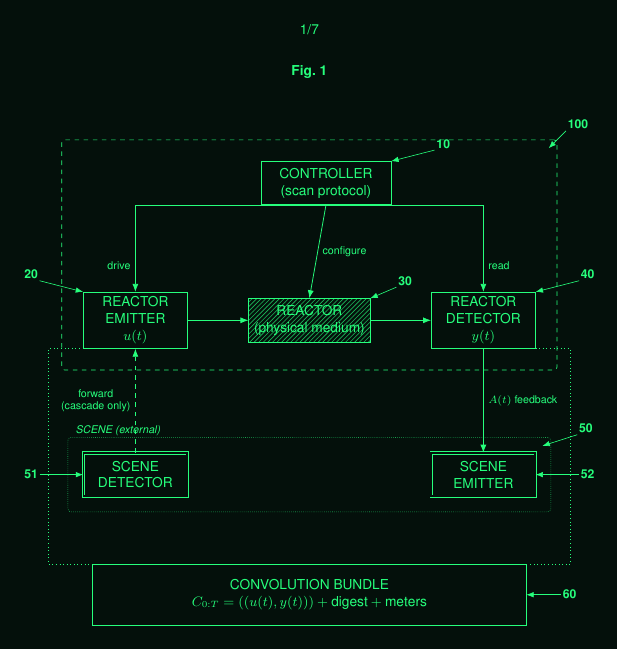
P.I.G.M.I.E. Filing 1 · Markov-Channel Apparatus · IPOI, filed 2026 · patent pendingThe canonical Reality Kernel is the minimal reference instrument. It has one steerable emitter, one detector, one controller, and one scene.
The emitter sends a single beam into the scene. The controller steers that beam along a committed, time-indexed scan law. The detector reads the returning response. The controller conditions later emission on the response already observed.
The record is built point by point as the beam traces its path. There is no pixel grid in the canonical model. There is only a beam on a programmed path. The canonical model is continuous and analogue: the sweep and the readout proceed without discrete framing.
This model plays the role that the basic feedback loop, or the textbook PID controller, plays in control theory. It is the clean ideal case from which messier instruments derive. It is not a claim that every real instrument has one beam and one detector.
Real instruments may replace the continuous sweep with discrete samples. They may replace the single detector with a pixel array. They may use detector arrays. They may use any synchronisable projector instead of a single steered beam. They may add a reactor. These are degenerate or elaborated cases of the canonical model.
A Reality Kernel is a closed physical loop. Emission and detection occur concurrently. The instrument is always probing and always observing.
The controller does not merely replay a fixed illumination pattern. It uses the ongoing detector response as an input to later control. The emitted signal is therefore conditioned on the physical response of the scene.
This distinguishes the instrument from a plain projector and camera. A projector can illuminate a scene. A camera can record a scene. The Reality Kernel adds the control loop that binds emitted probes and observed returns into one coupled process.
The scene is part of the loop. It is not only an object being imaged. It is a physical channel through which control, emission, propagation, response, and detection interact.
Emission and observation proceed together in time. The joint, time-ordered record of what was emitted and what was observed, across a run, is the convolution bundle. It names the joint history of control, emission, and response. The name is literal: the observed return is the emitted probe passed through, that is convolved with, the response of the scene and any reactor, so the bundle records an emit and observe pair whose relation is that physical convolution.
The bundle is committed together with a record of the protocol that was run and the bounds it was run within, so it can be audited afterward. This committed record of the protocol and its bounds is the protocol digest.
The convolution bundle is not merely an image. It is a record of the physical interaction that produced the image or measurement. A later evaluator can ask whether a recording is consistent with the controls, timing, and meter bounds under which it was produced.
This is a provenance claim about the physical interaction. It is not a claim about the semantic truth of the staged scene. If a real object, display, mask, or performance was present in the scene, the bundle concerns the light-in and light-out history of that interaction.
Formally, the Reality Kernel is a Markov kernel. A Markov kernel maps inputs to a distribution over possible outputs.
In the canonical case, the inputs are the scene and the committed control protocol. The output is a distribution over possible convolution bundles.
This formalism separates the apparatus from the channel it realises. The apparatus is the physical module. The kernel is the parameterised mapping induced by that module under its controls, hardware state, and measurement conditions.
The full notation is deferred to the formal section. At this stage the important point is simple. A Reality Kernel is not only a camera, not only a projector, and not only a scanner. It is a scene-coupled feedback channel with a recorded history of emitted probes and observed returns.
From here, the page mostly describes the research programme, not built systems. The grounded parts are the original WO filing and the demonstrated digital Truth Beam: the Truth Beam is built and recomputable, and the foundational projector-camera apparatus is the subject of WO. The formal model, the reactor families, and the networked embodiments set out below are enabled descriptions, published in Filing 1 and Filing 2 as part of that research project. Of these, only the basic physical apparatus has been explored so far, and only to a limited extent. The physical envelope is still being characterised.
A reactor is an optional physical medium added to the path. Its purpose is to make the channel empirically hard to reproduce under declared conditions.
A reactor may be a scattering plate, nonlinear film, phosphor screen, fibre-delay loop, biological tissue, or another physical medium with measurable response structure. Its value comes from memory, nonlinearity, manufacturing variation, or other physical behaviour that affects the observed bundle.
Hardness is not absolute. It is a measured property against a declared attacker family, budget, meter family, and time. It is expected to be re-measured as attackers improve.
A reactor is not required. A linear reactor is valid. An identity reactor is valid. In those cases the instrument remains a Reality Kernel, but physical hardness is not the main objective.
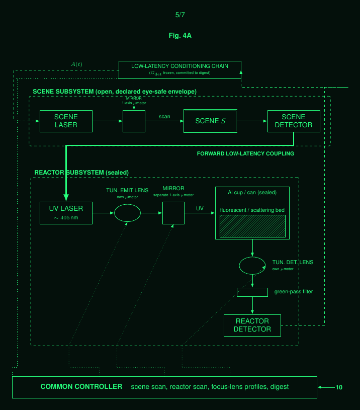
The one-dimensional bench realisation contains an open scene subsystem and a sealed reactor subsystem under a common controller. The scene subsystem contains a scene laser, a one-axis mirror, a scene, and a scene detector. The reactor subsystem contains a 405 nm ultraviolet source, tunable lenses, a sealed aluminium cup with fluorescent and scattering material, a green-pass filter, and a reactor detector.
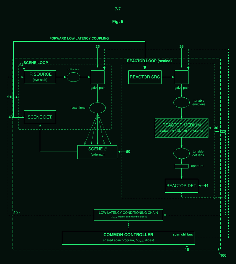
The two-dimensional apparatus generalises this structure. The scene loop contains an eye-safe infrared source, a collimator, a galvanometer pair, a scan lens, a scene, and a scene detector. The reactor loop contains a reactor source, a galvanometer pair, a tunable emitter lens, a reactor medium, a tunable detector lens, an aperture, and a reactor detector.
The signal A(t) denotes a feedback path from the reactor detector through a fixed conditioning chain to the scene or infrared source. It is a physical feedback signal used to condition later emission.
The canonical mode is closed-loop coupling to the external scene. A cascade coupling adds a forward, low-latency path from the scene detector to the reactor source. A parallel coupling omits that forward path and uses the A(t) path only. A scene-decoupled mode is PoliePuter operation, where the module is used as a self-contained physical computation channel. In this mode the loop is pointed at no external scene and used as a physical computer: the reactor's transform is the computation, for example an optical matrix multiply, so the same module that verifies, perceives, or renders can also compute.
The scan engine is the subsystem that steers and focuses the probe. In a typical optical realisation, two galvanometer mirrors steer the beam in X and Y. The scan law may be raster, Lissajous, spiral, or another declared path. Tunable lenses may follow a committed focus profile. Emitter focus and detector focus are controls, so the focal geometry is part of the recorded operation.
Filing 1 writes the kernel formally as P_theta, mapping a scene and a control history to a distribution over recorded bundles:
P_theta : S x U_{0:T} -> Dist(C_{0:T})Here S is the scene space. U_{0:T} is the control protocol over the interval from 0 to T. C_{0:T} is the space of convolution bundles recorded over that interval.
The parameter vector is theta = (theta_hw, theta_sw). The hardware parameters theta_hw include lens positions, gains, reactor state, mechanical configuration, and other physical settings. The software parameters theta_sw are the control and learned settings.
The instantaneous control is written u(t) = (s(t), e(t), g_det(t)). The term s(t) is the scan state. The term e(t) is the emission state, including intensity, wavelength, polarisation, and related source controls where present. The term g_det(t) is the detector gain or detector-side measurement setting.
Some hardware-associated parameters may be trainable. In the two-dimensional anchor, the trainable subset can include the scan law, emitter focus, detector focus, aperture, drive amplitude, and coupling gain.
The channel is not assumed to be memoryless. It is also not claimed to be exactly Markovian at the physical level. A declared mixing condition bounds the residual dependence on earlier history. Beyond a horizon L, the residual dependence stays below eps_mem, written nu_mix(u; L) ≤ eps_mem. Because the kernel conditions on the full committed control history, it is well-defined even though the underlying physics has memory, and the mixing condition is what licenses approximating it with a finite-horizon model. Physically, the channel mixes because the medium dissipates and relaxes, so the influence of an earlier emission decays over time; a channel that did not mix, such as a perfect lossless memory, would not admit this finite-horizon approximation.
Empirical hardness measures how difficult it is to reproduce a valid-looking convolution bundle under declared conditions. The declaration includes the attacker family, the available budget, the meter family, the latency bounds, and the evaluation threshold.
Hardness is a property of an instrument, a protocol, and an evaluation setting. It is not a universal property of the name Reality Kernel. A configuration without a reactor, or without a strong meter envelope, may have lower hardness.
A witness mesh is a deployment in which several Reality Kernel modules are linked by continuous, low-latency analogue couplings. The participating instruments exchange derived fast-loop signals over bounded-latency paths. Their joint records are evaluated together.
Temporal order in the analogue kernel is established by mutual analogue timestamping between participating instruments. This has no obligatory discrete or cryptographic component.
A discrepancy test compares a claimed recording against the declared protocol, meter envelope, latency budget, and threshold. The result is conditional on those declarations.
The Truth Beam is the verification objective family. It checks whether a recording is consistent with a real physical device, scene, and control protocol. It concerns the provenance of the physical interaction, not the semantic truth of the scene. One discrete digital instance is documented separately at truthbeam.com.
The Limager is the perception objective family. It covers active sensing, 3D sensing, and semantic analysis of physical responses.
The Reality Transform is the controllable rendering objective family. It uses the physical channel to drive projection, illumination, or son-et-lumiere style mappings constrained to the measured channel.
Yoked operation is not a fourth objective family. It is a modifier. In yoked operation, the device and the scene are driven toward a joint dynamical state.
The same kernel formalism covers digital and analogue embodiments.
A digital embodiment may use a synchronised projector and camera. In that case, many points are illuminated and read through an array rather than swept by one beam and one detector. This is a degenerate case of the canonical model.
An analogue embodiment may use continuous optical and radio-frequency paths. Probe and response are exchanged as physical signals. Timing is established by mutual analogue timestamping between participating instruments.
The analogue and continuous optical embodiments are described and enabled in the filings. The physical envelope is still being characterised.
The two embodiments operate independently. They are intended to merge only at the optical layer.
truthbeam.com · the demonstrated digital instance.
Filing 1: Physical Markov-Channel Apparatus · the IPOI application (on IPFS).
WO 2025/046153 A2 · the foundational projector-camera apparatus, first filed 2023 and published as this PCT.